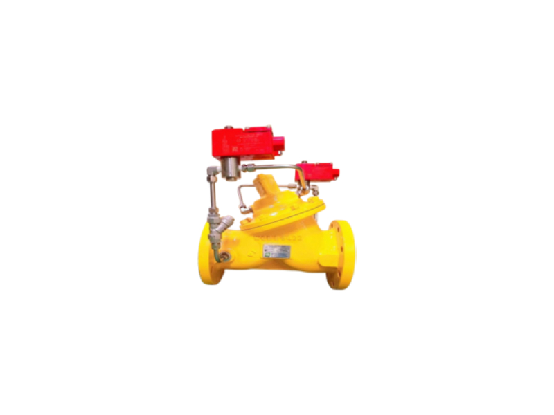
Diaphragm Digital Control Valves
Diaphragm Digital Control Valve is an electrically actuated, hydraulically operated multi-function control valve. It can be used for local as well as remote controlled batching operations with electronic batch controller. The valve also offers an in-built flow governing function.
DESIGN FEATURES
- Precision multi-stage opening and closing
- Fail-safe design
- Low pressure drop
- Bubble-tight seat design
- Flow rate control
PRINCIPLE OF OPERATION
The Diaphragm Digital Control Valve basically consists of a diaphragm operated main valve and two solenoid valves. Normally open (NO) solenoid connects the valve cover chamber to the upstream pressure, whereas normally closed (NC) solenoid connects the valve cover chamber to the downstream pressure.
When the Diaphragm Digital Control Valve is used with an electronic batch controller, it can be digitally controlled by operating the solenoid valves through any of these three stages :
- when NO and NC solenoids are energized, the valve opens gradually.
- when NC solenoid is de-energized (keeping NO solenoid energized), the valve locks at its current position.
- when NO and NC solenoids are de-energized, the valve closes gradually.
The operation of the valve is simple and is explained below. The total batch quantity delivered and controlled through the valve is divided into 7 stages (Refer graph) for the purpose of convenience.
Initially both NO and NC solenoid valves are in de-energized condition. The NO valve applies high upstream pressure on the diaphragm, whereas the NC valve prevents this pressure from getting drained to the downstream side. The valve remains close as a result of this.
Stage 1
Both NO and NC solenoids are energized. NO valve now restricts the high upstream pressure from entering into the cover chamber. NC valve permits the pressure above the diaphragm to vent to the low downstream pressure. This creates a differential pressure across the diaphragm, the high upstream pressure acting from below the diaphragm opens the main valve and allows the flow to start through the valve.
Stage 2
As the flow rate reaches predefined value (set in the batch controller as “Low Flow Start”) the NC valve is de-energized. This prevents further draining of the chamber and locks the valve at this flow rate. Initial delivery at slow speed avoids splashing of product and also avoids the generation of static charge.
Stage 3
When sufficient quantity is delivered at the slow speed, the NC valve is energized again. This allows further draining of the chamber and hence increases the flow.
Stage 4
When the flow reaches to the maximum level (set in the batch controller), the NC solenoid is de-energized. This maintains the constant high flow rate for the remaining batch. During this stage, the flow rate control is done by the batch controller. When a number of flow meters are connected to the same pump, stopping (or starting) one or more meters increases (or decreases) the flow rate at the remaining meters. When the flow rate increases, the NO solenoid is energized momentarily. This injects some high pressure in the cover chamber and makes the valve to throttle in order to maintain the set flow rate. If the flow rate decreases, the NC solenoid is energized momentarily. This allows slight draining of the chamber and allows the valve to open further in order to maintain the set flow rate.
Stage 5
At the end of the batch, the NO solenoid is de-energized. This injects high upstream pressure into the cover chamber and throttles the valve.
Stage 6
When the valve throttles sufficiently to achieve the predefined slow closing flow rate (set in the batch controller), the NO solenoid is energized. This maintains the uniform flow rate.
Stage 7
When the batch quantity is delivered, the NO solenoid is de-energized. (NC solenoid is already de-energized.) This applies high upstream pressure into the cover chamber, which makes the main valve to close completely to achieve bubble-tight shut-off.
Note: The number of stages during opening and closing are programmed in the batch controller and can be as many as desired. One stage during opening and two during closing are recommended.
Caution: Sufficient pumping flow rate should be available to achieve the flow parameters set in the electronic batch controller. In the absence of this, there are chances of delayed response in closure, resulting in valve over-run.


